Engineering 100-980
Lab 1: Arduino 101
You should work on this assignment in pairs, but you must SUBMIT YOUR OWN INDIVIDUAL WORK. Aside from hardware photos, all submitted content must be your original work and not copied from anyone else. Submissions that are not your own may result IN POINT DEDUCTION OR A ZERO.
Contents
Materials
For this lab, you will need:
- 1 Arduino Nano Every
- 1 Breadboard
- 1 Programming Cable (and adapters if necessary)
- 6 LEDs
- 2 1k\(\Omega\) resistors
- A hand-full of jumper wires (it is possible to do the whole lab without any)
- A computer with the Arduino IDE installed and setup.
Introduction
You will be given feedback (and later graded) on your use of color coding when wiring breadboard circuits. Please take careful note of the guidelines listed below!
- Red: Power (5v, 3.3v, etc.)
- Black: Ground
- Blue: Analog (Pins labeled with an A, and most likely used for analogRead or sensor data)
- Yellow: Digital (Pins labeled with a D, most likely used to control things or for more complicated sensors)
Use of vertical breadboard rails: Utilize the breadboard rails (blue and red) to run power and ground lines for easy access across the entire breadboard. For example, run a black jumper cabled from the Arduino ground pin to one of the blue rails, and then connect another black jumper from the grounded blue rail to the other blue rail. Now both blue rails are grounded, and can be used as the ground terminal for any components. Similarly, you could connect a red jumper from the 5v pin on the Arduino to one of the red rails, and use that rail for a 5v supply. In future labs, when we’re working with 5v and 3.3v, we will have you run a rail for each voltage.
Welcome to ENGR100-980! Over the course of the next semester, you will be designing and building your own circuit board, complete with measurement instruments to gather information on acceleration and pressure (altitude!) data. To get to that point, we will spend the first several labs learning about various components and eventually how to combine them into a cohesive system.
In lecture, you’ve had a crash course on the ins and outs of micro-controllers. Now, you’ll be working with your own Arduino Nano Every micro-controller so you can begin to learn how to use it. The Nano Every will be the brain of your payload; it is very well-suited to these sorts of applications, as you will see.
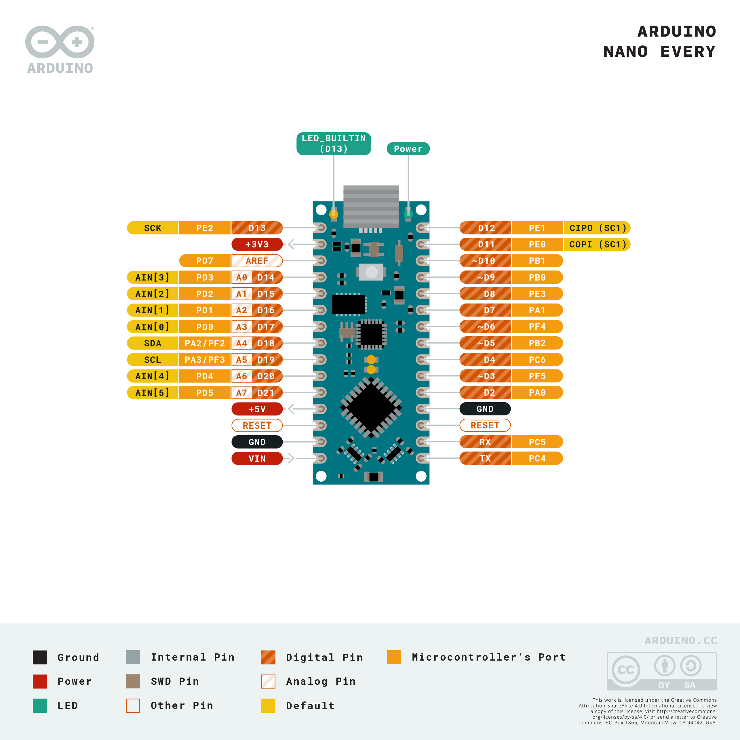
The IO pins on the Nano Every each serve different purposes. Above, and in resources, is a helpful diagram detailing the types of pins on the board.
In general, the digital pins are on one side (D2 - D13), and the analog pins are on the other (A0 - A7). Digital pins only read and write binary values - HIGH (5V) or LOW (0V). Analog pins can also write these binary values. However, analog pins can read more than just binary values. They read a range of analog values from 0V - 5V. An analog pin reads the voltage that it “sees” on the circuit or sensor you connect it to.
Finally, it’s worth noting the GND pin. Voltage values are read with respect to some constant reference. They are relative, not absolute. This reference is usually called ‘Ground.’ There should ALWAYS be a ground connection on every circuit you make, whether you are using a micro-controller or not. This is essential when dealing with electricity, to make sure that things don’t spark or get fried because they draw too much power.
Before building any circuit, always sketch your design first. The components below are the essential ones you’ll be working with most throughout this semester.

- Resistor (RES) — limits the flow of current in a circuit. Measured in ohms (Ω), resistors protect components from receiving too much current.
- Capacitor (CAP) — stores and releases electrical energy. Capacitors are commonly used to smooth out voltage fluctuations or filter signals.
- Diode — allows current to flow in only one direction. This makes diodes useful for protecting circuits from accidental reverse current. A special type of diode is the LED (Light Emitting Diode), which emits light when current flows through it. Like all diodes, LEDs are polarized — current must enter through the positive leg (anode) and exit through the negative leg (cathode), or the LED will not light up.
- Ground (GND) — the common reference point (0V) for all voltage measurements in a circuit. Every circuit must have a ground connection.
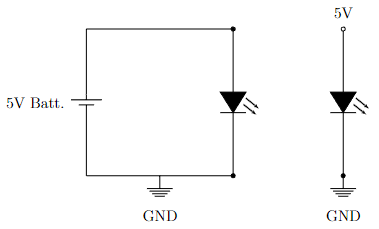
To illustrate, consider the simple LED circuit shown below, where a 5V supply powers a bulb, which is attached to GND. The two circuits shown are actually equivalent representations of the same thing. In the circuit on the left, the 5-volt battery raises the top half of the loop 5 volts higher than the bottom half. The bottom half of the loop is held at zero volts, since it is grounded. Current flows clockwise from the positive (top) to the negative (bottom) terminals of the battery.
In the circuit on the right, the top node is held at 5V by some unseen source, and the bottom is held at 0V because it is grounded. The current flows down, into the grounded node. This representation works great if you want to analyze a fragment from a larger circuit.
Procedure
1. The Breadboard
Before actually launching into the building of circuits, it’s important to understand the tools that you are working with. Your breadboard will act as the “circuit board” on which you build your systems. Notice that it is organized by enumerated rows and columns.
The pins of your electronic devices plug into the holes on the breadboard. To use it effectively, you need to know which holes are electrically connected to each other — and just as importantly, which ones are not. The diagram below highlights the two types of connections inside the board:
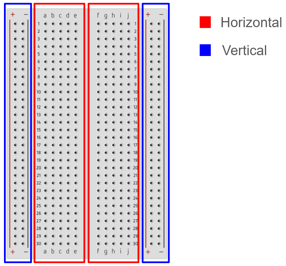
Horizontal connections (red regions): Inside each red region, the five holes in any given numbered row are electrically connected. For example, holes a1, b1, c1, d1, and e1 all share the same node — plug a wire into any one of them, and that signal is available at the other four. The same applies to f1 – j1, and so on for every numbered row.
Note: the left red region (columns a – e) and the right red region (columns f – j) are not connected to each other. The gap down the middle of the board separates them. So a1 and f1 are on different nodes, even though they sit on the same numbered row.
Vertical connections (blue regions): The four narrow strips along the outer edges, marked with “+” and “−”, are the power rails. Every hole in a single “+” column is connected together along the entire length of the board, and the same is true for each “−” column. These rails make it easy to distribute power and ground around your circuit without running a separate wire from the Arduino to every component.
Note: the left “+” rail and the right “+” rail are separate nodes. They aren’t automatically connected to each other - if you want both rails at the same voltage, you have to add a jumper wire between them yourself. The same goes for the two “−” rails. Usually for the “+” rails, you will have two different voltages, 5V and 3.3V as you will see later in the semester.
So in practice: if you connect the Arduino’s 5V pin to any hole in one of the “+” rails, every other hole in that same rail is now at 5V. From there, a short jumper from the rail to any row gives that row 5V — much cleaner than running a dedicated wire from the Arduino for each component.
Here is a helpful video on breadboards
Circuit elements are connected in breadboards by placing their legs into holes that share the same row. In this way, devices can be chained together to create complex circuits. An example is shown below — a voltage divider made from two resistors connected end to end.
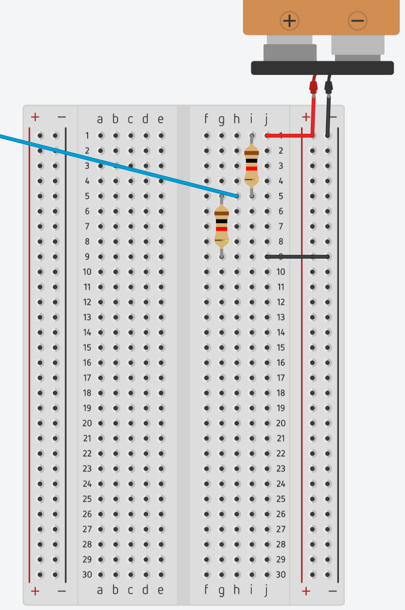
Tracing the circuit in the image:
- The battery’s positive terminal connects to the right + power rail and there is also a red wire that goes to j1.
- R1 (top resistor) sits in column i. Its top leg is in row 1 and is in the same row as the red wire, so it receives the supply voltage.
- R2 (bottom resistor) sits in column g. Its bottom leg is in row 9 and is connected to the − rail by a black wire, giving it a path to ground.
- The two resistors share row 5 — R1’s bottom leg and R2’s top leg are both in row 5, connecting them together. This shared node is the output of the voltage divider.
- A blue jumper wire runs from that shared node (h5) to whatever component needs the divided voltage.
A formal circuit diagram of a voltage divider is shown later in this manual, and in resources.
Your lab instructors will demonstrate using a breadboard before the lab begins. If you have questions about whether or not you are connecting devices appropriately, please don’t hesitate to ask.
The image below shows the inner workings of a breadboard. Hopefully this demystifies the connections inside of the plastic housing for you.
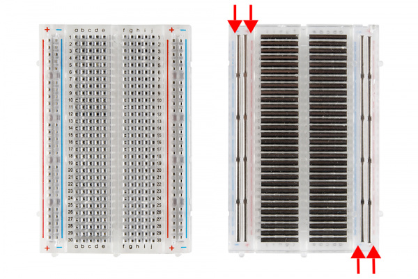
Inside the plastic housing, the breadboard is made up of metal clips that run in two directions, horizontal and vertical. When you push a component leg or wire into a hole, it presses against the metal clip inside, making contact with everything else connected to that same strip. No soldering needed — the friction hold is strong enough for prototyping.
-
Check out the first half of this video. (You may stop the video at 2:33) This shows how to connect an LED to the 5V output pin of the Arduino, a resistor, and then to ground. This circuit will work without any Arduino code at all and is a good test for the circuit board and powering the Arduino! This is the circuit you will build in step 2.
-
Build the LED circuit shown in the schematic below. When built, it should look similar to the voltage divider circuit, except one of the resistors will now be an LED. Be aware that LEDs only turn on when placed in your circuit in the correct orientation. Try switching the orientation of your LED if it doesn’t turn on after completing step 2.
Hint: one leg is longer than the other! Check the resources page for more…
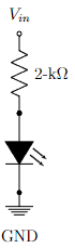
Note: Vin refers to the 5V pin on the Arduino for now. We will move this in 2.3 below.
-
Turn on the Arduino by plugging in the mini USB cord into the device and the USB into the computer. Note that an LED built into the micro-controller should begin glowing. The LED you connected to the Arduino should also begin to glow if your circuit is correct.
-
To run any code on the Arduino, you will need to set your environment. Open up the Arduino IDE on your computer. We will need to add a library to access the starter code for our class. To setup your Arduino IDE and required library, follow the instructions in tutorials.
-
Make sure the correct board is connected under the “Tools” menu. The board should be “Arduino Nano Every”. You might have to change the selected port if the IDE is failing to find the board.
Do not continue to the next section unless you can see your Arduino Nano Every and its port in your Arduino IDE, and there are LED(s) on its board that are lit up.
2. LED Blink
- Check out this video that walks you through how to do this part.
- Let’s run our first code. Navigate to
File → Examples → ENGR100-980 → Lab1-LED. A new window should open up, with some code on it. (Make sure to set the proper micro-controller and processor under the Tools menu). Upload and run the code, and observe what happens. - Now, let’s try making an external LED blink instead of the built-in one. To do this, connect your LED and resistor circuit’s positive side to one of the digital pins on the Arduino. Make sure you modify the code such that
#define LED_PIN_0 ?replaces “?” with the pin number you are plugged into. For example, D7 would replace “?” with “7”. - Once this works, we are going to connect 5 more LEDs all to different pins. Your goal here is to take your new knowledge about breadboards to connect all 6 of your LEDs to your breadboard while using only 1 resistor. (Each LED still needs to be connected through a resistor though!) Now edit the code, using the existing lines as context, to make all 6 LEDs (not the built-in LED) flash in a wave pattern (Knightrider).
-
Upload this code and again observe that the same behavior happens, but this time on the external LED as well. Now, take a picture of your breadboard in its working state. This will be included in your submission later.
REMEMBER TO TAKE A PICTURE, YOU WILL BE SUBMITTING IT!
-
When someone around you is ready to help you with this step, unplug your Arduinos and breadboards from your computers and swap them with a neighbor. Each of you should move one wire on each other’s circuit without the other person watching. Hand each others boards back and attempt to diagnose what the other person changed in your board. Take a picture of this new board state to include in your submission. Once you believe you have fixed the issue, consult your original photo to ensure everything is wired as it was. Now, plug the Arduino and breadboard back into your computer and verify the LED still flashes as expected.
Note: If you are having trouble finding a partner, you do not need to swap with someone, simply having someone else change your board without you watching will suffice.
AGAIN, DON’T FORGET THE PICTURE FOR YOUR SUBMISSION.
3. Voltage Divider
Consider a voltage divider shown below. The output voltage is related to the input voltage through the equation
\[V_{out} = \frac{R_2}{R_1 + R_2} V_{in}\]Note: The order of the resistors here matters a great deal, getting them confused will lead you to the wrong value.
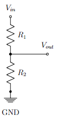
The concept of the voltage divider can be extended to any number of resistors. The output voltage at each node is simply the total resistance below that node divided by the total resistance of the circuit. As you might have guessed from the formula, when resistances are placed in-series like so, their resistances add. Make sure you understand the concept, you’ll need it for future labs.
-
Disassemble any circuits you have from the previous parts of the lab.
-
Plug a wire directly from the 5V line of the Arduino to the A1 pin of the Arduino.
- Go to File → Examples → ENGR100-980 → “Lab1-Voltage-Divider” to open the starter code for this section.
- Here we will use the
analogRead()function to read in the voltage. - To send the data back from the Arduino to your computer our sample codes uses
Serial. First it specifiesSerial.begin(9600)to initiate communications between the Arduino and your computer. The “9600” specifies the baud rate, and lets the Arduino know how fast to send data to the computer. Then, to actually transmit data, we useSerial.print(dataHere). The variabledataHerecan be data of many types, including integers, doubles, and character arrays.
- Here we will use the
- To see the data sent from the Arduino to the computer, open the Serial monitor inside of the Arduino IDE. This can be done by clicking the magnifying glass in the top, right-hand corner of the IDE.
- At the bottom of the Serial monitor, make sure the baud rate is set at 9600 to match the Arduino.
- Record the value returned by
analogRead(), as you’ll need it later.
- Build a voltage divider by setting \(V_{in}\) as the 5V line of the Arduino, have \(R_1\) be 1k\(\Omega\) and \(R_2\) be 1k\(\Omega\).
- Plug \(V_{out}\) into A1 of the Arduino.
- Resistance is denoted by a band color code, which you should get used to reading. Check the chart in resources for info and data on how to read resistances of resistors using their colors.
- Our code uses the
analogRead()function to read in the voltage and record the raw number that the function returns.
- Try playing with various resistor values, and take down the values from two more combinations of resistors. Make sure to write down the resistor combinations as well as the analog output for both of your additional experiments.
- Come up with a combination of resistors that will result in an output voltage of less than 1.25V.
- You can convert the raw output from
analogRead()into voltage values by multiplying by \(\frac{5}{1023}\). - You will learn why in lab 3! Try it and see if it works.
- You can convert the raw output from
Post-Lab Questions
- Write a short explanation of what your peer changed on your breadboard and why you think this would cause it to not work as normal (or, why you think their change would not have impacted anything).
- What combination of resistors did you use to get to less than 1.25V at the analog pin in step 3.7? Draw them in a circuit and upload/attach a picture of this circuit to make it clear where you put the resistors.
- Using three resistors in series, draw a voltage divider circuit with two \(V_{out}\)s (one between resistors 1 and 2 and one between resistors 2 and 3). \(V_{out1}\) should be equal to \(\frac{2}{3} V_{in}\) and \(V_{out2}\) should be equal to \(\frac{1}{3} V_{in}\). Give possible values those resistors could take. What would happen if we doubled the value of all of the resistors?
Hint: Resistors in series add together. So, if you have three resistors that are each 100\(\Omega\), and measured the voltage between the first and second resistors, the voltage divider circuit would have 100\(\Omega\) on one side and 200\(\Omega\) on the other side.
Submission
Reminder: You should work on this assignment in pairs, but you must SUBMIT YOUR OWN INDIVIDUAL WORK. Aside from hardware photos, all submitted content must be your original work and not copied from anyone else. Submissions that are not your own may result IN POINT DEDUCTION OR A ZERO.
On Canvas, you will submit ONE PDF that will include all of the following:
- A picture of your breadboard with an external LED on it being lit up while plugged into an Arduino. (You’ll receive full points for submitting this. We will simply be using it to give feedback on color coding in preparation for stricter grading in later labs.)
- A photo of your breadboard (unplugged from your computer) in its broken state.
- Written post-lab answers for questions 1-3.
- 2 circuit diagrams (i.e., schematics) in total for post-lab questions 2 and 3.
To put said content into a PDF, it is suggested you create a new Google Doc and paste your images and write your text in the document. Export/Download this document as a PDF and upload it. DO NOT SUBMIT A GOOGLE DOC FILE.
Submitting anything other than a single PDF may result in your work not being graded or your scores being heavily delayed.