Engineering 100-980
Contents
Sensor Board Documentation
Because you are going to be using the sensor board that the staff designed for your project, we thought it would be best to also give you some documentation on the board.
Sensor Pin Connections
Here is the schematic for the rocket boards. Take note of voltages, resistance values, etc. Take note of what sensor is connected to which Arduino pin as it may be different from what is currently in your code, and may require updates.

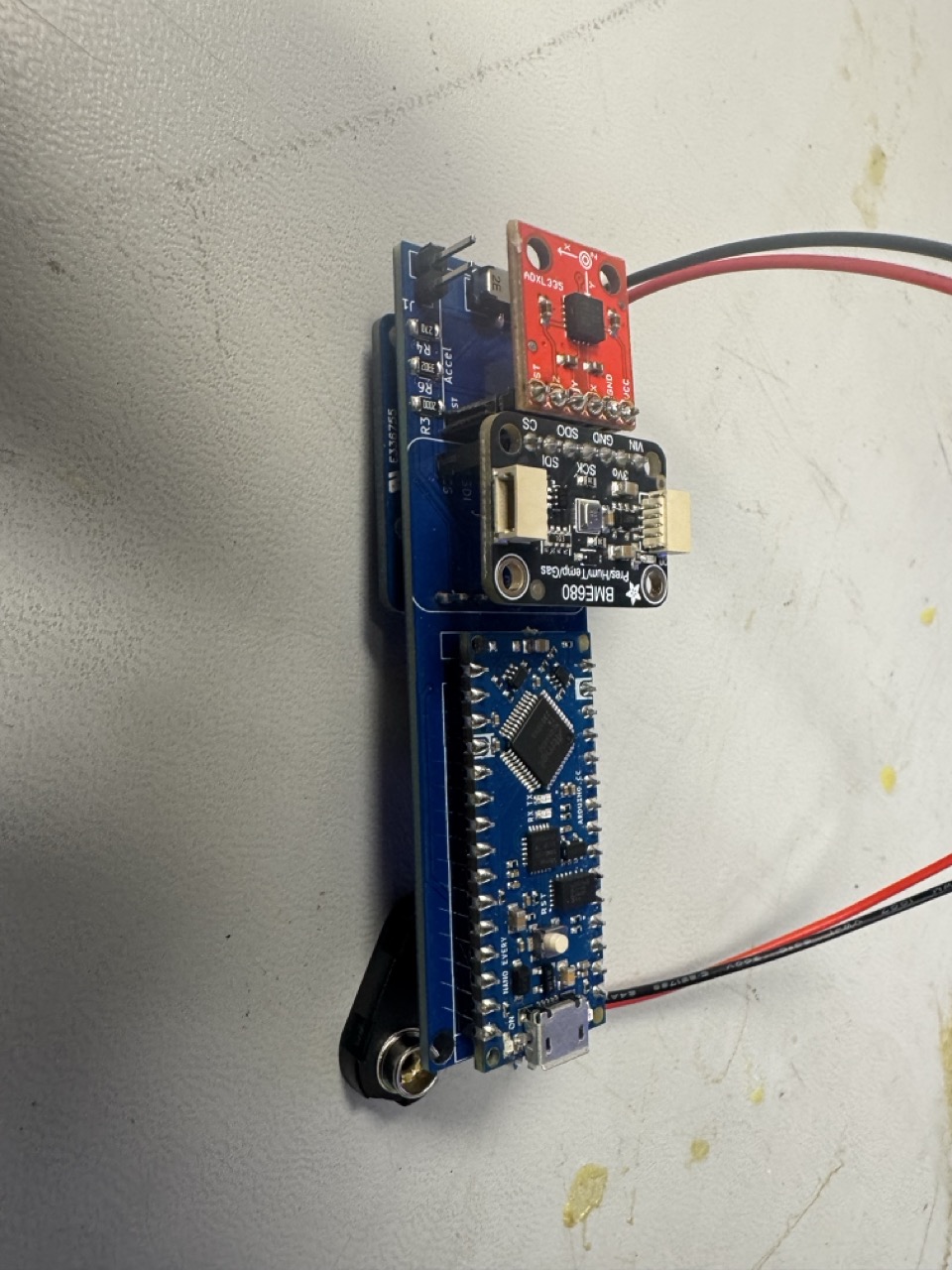
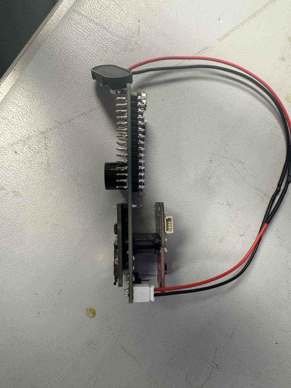
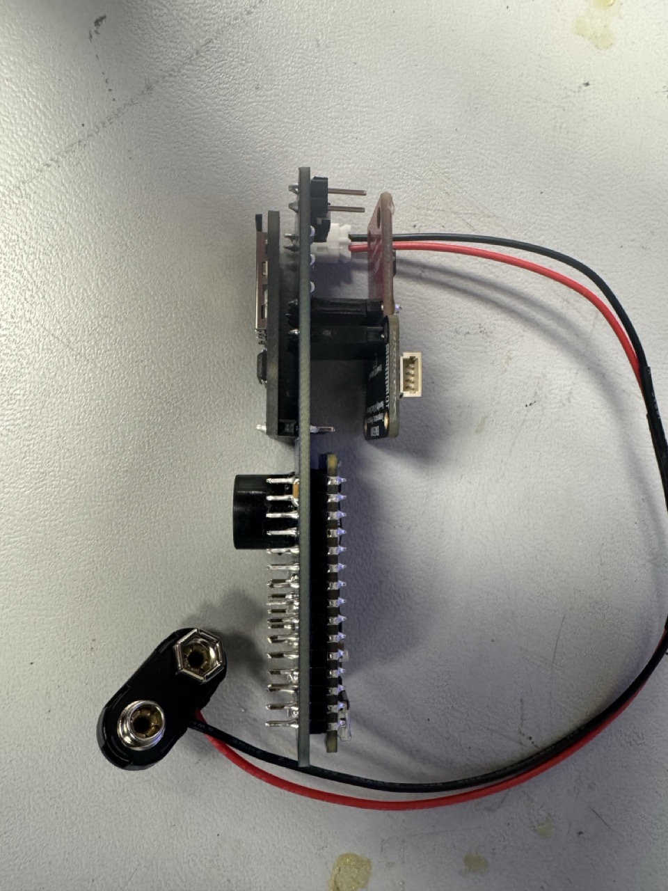
Board Example
READ THIS VERY CAREFULLY: Make sure that you ADD headers to the arduino. Other than this, your PCB board should look identical to the example below. The SD Card can be soldered on directly to the board as seen on the example below.


Standard Operation
When fully assembled, the rocket board records various sensor measurements and drives 5 LEDs. The device draws power from a battery, connected to the JST connector. Power is controlled by the SMD switch.
When the device is powered on via that switch, it’s in a “ready” mode. In order to actually begin data collection, you must pull pin D2 to ground briefly. This tells the Arduino that it’s time for launch. You’ll find holes for D2 and GND labelled J1. How should you do this? It’s up to your team! You can solder a button onto wires going to the board, make a spot to put a small jumper wire, whatever you want (within reason, of course). The only requirement is that you must be able to start recording data while the board is packed away inside the rocket. Ensuring that no wires are loosely hanging off your rocket during launch isn’t a requirement, but this could tangle your parachute or cause other issues. (Tape will be your friend here)
Just like in lab, the data will be saved to an SD card. Nothing special there.
Hardware Remarks
Assembly Tips
Now that you can see how everything goes together, let’s look at a few important details to remember:
- Solder female headers in for the accelerometer, BME680, and Arduino. If space allows, do this for the SD logger as well (most likely not…).
- You cannot mix around the LED positions without paying very close attention to the current limiting resistors. If you solder the wrong resistor value to an LED it will do one of two things: be too bright and burn out, or dim and not visible. We highly recommend reading carefully over the locations of the LEDs, and making sure of their positions before soldering anything. We will NOT be replacing LEDs that get burnt out due to mismatched positions.
READ THIS VERY CAREFULLY: All 5 LEDs have the same footprint, symbol, style, etc. They are made by the same manufacturer, they are even in the same product line with consecutive part numbers. BUT they do not necessarily have the same indications for positive and negative (anode/cathode) sides. For every individual LED you must carefully check the datasheet to confirm its correct orientation, and do not assume it will be the same as the others (because they are not…). The datasheets for every part you are working with is included below in the resources section.
Technical Drawing
In the figure below you’ll find the schematic of the inner copper layers and edge cuts.

Sensor Board Files
Component Spec Sheets
Link to BME680 Arduino Library Documentation
Link to SD Logger Documentation
Async for BME680
Everytime the BME680 does a reading, it blocks all other inputs from happening. This causes a delay between 300 ms - 500 ms. To fix this we have to use async functions.
An async function is a type of function in programming that allows for asynchronous operations, meaning it can perform tasks without blocking the execution of other code.
The three main functions that you will need to use are beginReading(), endReading(), and remainingReadingMillis(). You can read the documentation of these functions here
You will have to do something along these lines
bme.beginReading();
if(bme.remainingReadingMillis() == 0){
    bme.endReading();
    //print out any sensor values or add to datastring, up to you
    //you can get the specific values you want by doing
    //bme.temperature, bme.pressure, bme.humidity, bme.gas_resistance
}
else{
    //do nothing or whatever you want
}
In words, this code:
- Starts an async function,
beginReading(). - Checks if the async function is done by checking if
remainingReadingMillis()equals 0. - If it is done, we end the reading using
endReading(), which defines all environment variables (temperature, pressure, humidity, and gas_resistance). Optionally, you would print the values out to the SD logger, store it into the data string, or just set them equal to a variable that you can then use later on. Totally up to you how you approach this! - If it is not done, then we do nothing or whatever you want, we just want to be able to move down and read the other sensor values.
This makes your code non-blocking for the BME680 functions.
Next Steps
- Assemble the board!
- Figure out how you’ll mount it within your rocket
- Figure out how you’d like to collect data using Arduino IDE
As always, don’t hesitate to reach out to the IAs if you need help, or have any questions! If you do NOT plan accordingly, this class can get overwhelming. Office hours and slack are your best friends