Engineering 100-980
Solder Challenge
Contents
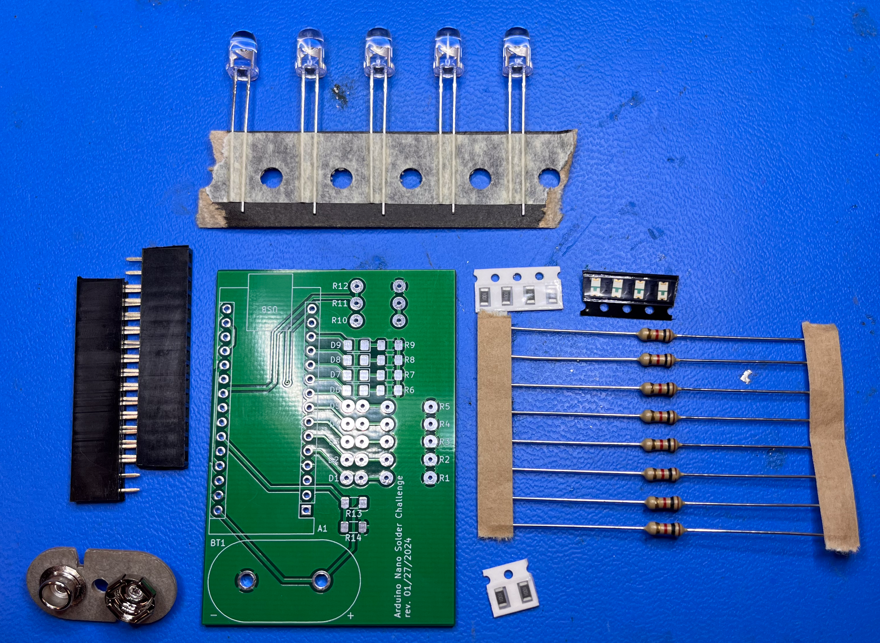
Materials
All of these materials are presorted into the correct number you need in the solder lab bins. Take ONE “bundle” of each component unless stated otherwise.
- 1 Solder Challenge PCB
- 1 Arduino with Solder-Tester code uploaded from ENGR100-980 library (don’t worry about this item until you are done soldering)
- 8 1k\(\Omega\) Through-Hole Resistors
- 6 1k\(\Omega\) Surface Mount Resistors (1001 Resistors)
- 5 Through-Hole LEDs
- 4 Surface Mount LEDs
- 1 9v Battery Connector
- 2 15 Pin Headers
General Tips and Tricks
READ ALL OF THESE ITEMS CAREFULLY. DO NOT SKIP ANY OF THESE ITEMS.
- A common misconception when soldering exists around where you should apply the heat from the iron.
- You are NOT simply applying heat to the solder wire. If you try to solder by only heating the wire, you are working against surface tension and it is likely all of your solder will stick to either the iron or the pin of the component you are soldering.
-
You ARE trying to heat the pad, or the through-hole, simultaneously with the pin of the component you are placing. Any two components you want soldered together (aka the PCB to the component) should both be heated so that the solder flows between them and thoroughly joins them together.
-
You should directly place a very small amount of solder on the tip of the iron, so that the surface of the iron doing the heating is increased. This way, when you place the tip of the iron on the pad or through-hole, there is a larger surface area of heat being applied, providing a nice path for the solder to flow on.
- If the tip of your soldering iron is very dark, or looks crusty, you need to clean it! You may use the wire wool and lightly “scrape” off any contaminants, excess solder, or excess flux. You may also “tin” the tip of the iron one of two ways:
- Apply a larger amount of solder to the tip of the iron to “coat” it in solder. The flux/rosin inside the solder wire will act as a sort of cleaning agent on the iron. After coating, use the wire wool to scrape off all excess material. Your iron should be shinier now!
- Lightly press the tip into a can of tinning solder. Make sure the tip of the iron is thoroughly scraped clean before doing so, to avoid leaving drops of old solder in the can. Then scrape the iron in the wire wool to clean off any excess material.
- ALWAYS use the carbon filter fans to absorb smoke from the iron and burning flux. It’s not fun to breathe this smoke for long periods of time…
- Please… DO NOT try to wipe the iron on the carbon filters, this ruins them.
-
DO NOT try cleaning your iron with the sponge if it is not damp… this is (should be) self explanatory. If you do decide to use the damp sponge as a cleaner, do not do it very often or for long periods of time. The irons have a ceramic heating element with a metal cover. Going from extreme heat to extreme cold is hard on these materials.
- Wear safety glasses while soldering!
Procedure
- Turn on the carbon filter fan, and turn on the soldering iron. It will begin to heat up, and should stop at a value of somewhere around 700 degrees Fahrenheit. If not, check with an instructor for help changing the temperature.
The most common mixture for soldering wire contains lead. When heating leaded solder, the working temperature hovers somewhere around 600 degrees Fahrenheit. When working with unleaded solder the melting point is higher, and thus requires a slightly higher temperature to maintain sufficient heating. This explains the higher temperatures we use with our irons in this lab.
- Gather your materials from the list at the beginning of the document. They are separated for you, so you shouldn’t need to cut any packaging or tape rolls.
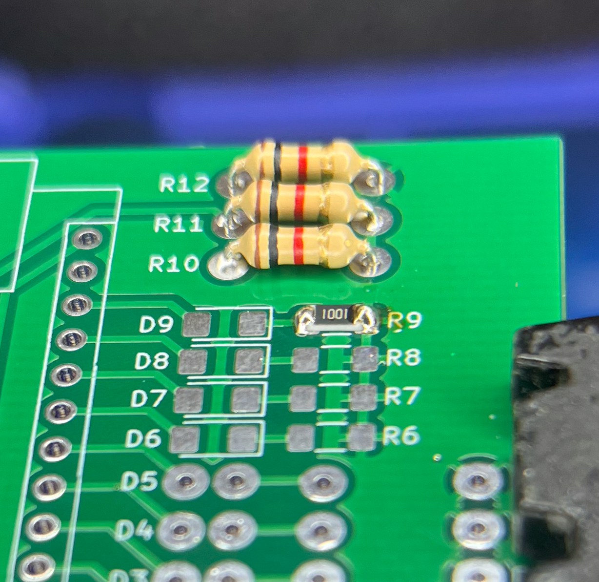
- Insert a through-hole resistor into the PCB at the top of the board, into the holes labeled for R12. Spread the pins on the back-side of the board to hold the component in place. Note that polarity doesn’t matter for resistors.
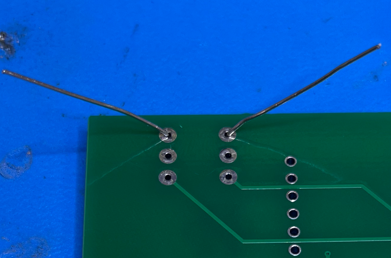
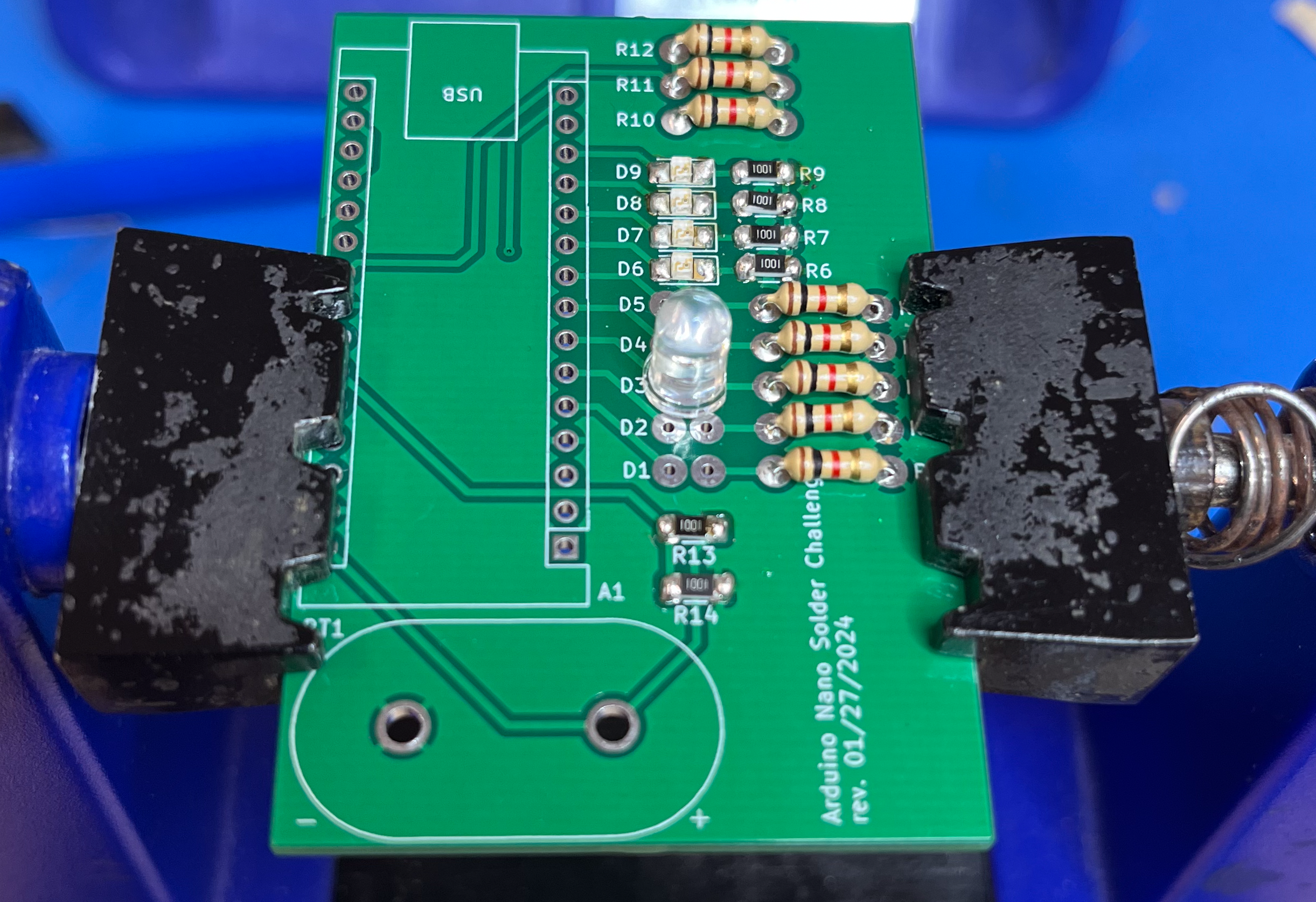
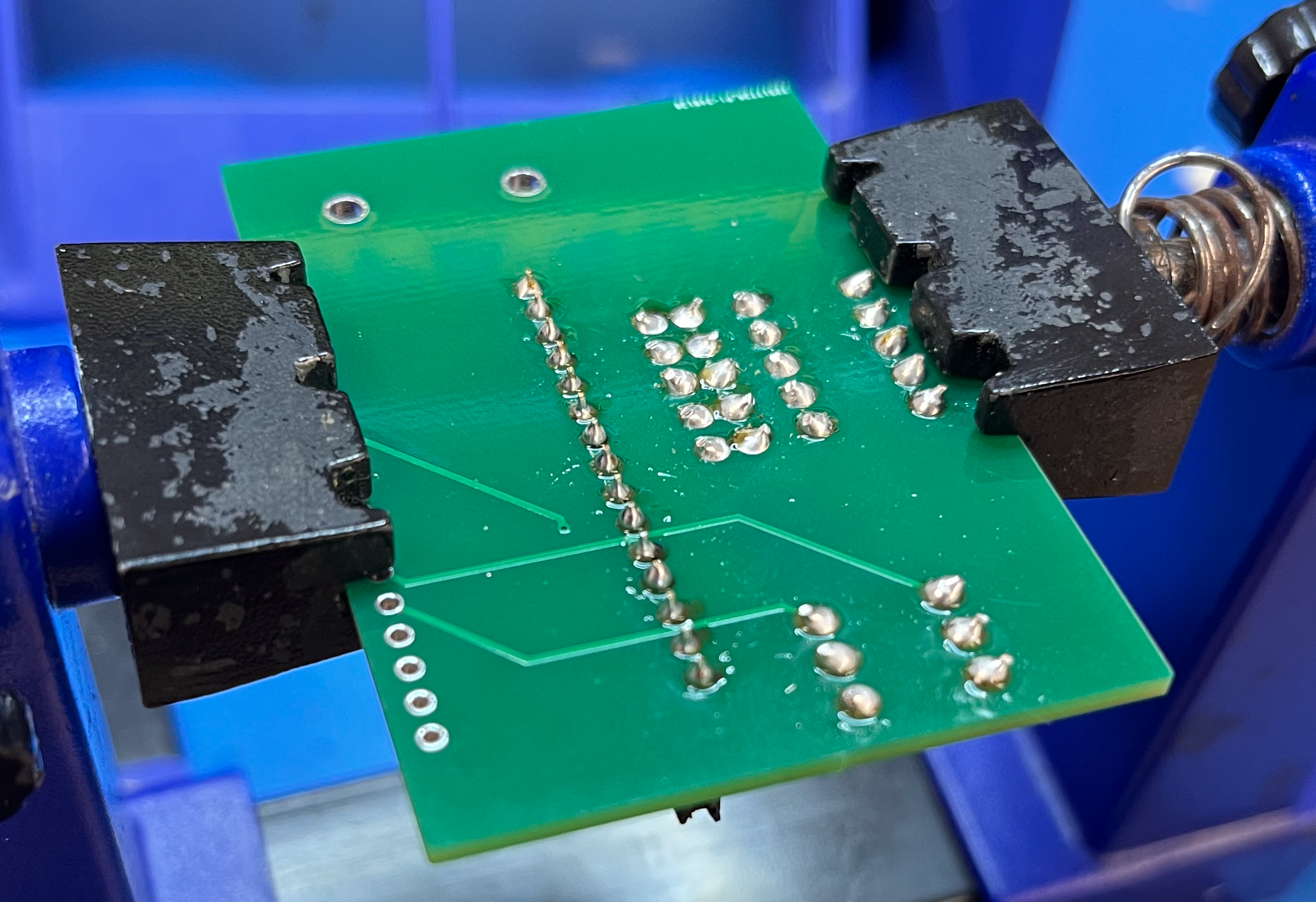
- Place a very small amount of solder wire on the tip of the iron, and using this small “ball” of solder, heat the pin and hole lightly feeding solder into the hole. If the solder sticks to the pin and doesn’t flow through the hole, this is a problem. You need to heat the pad of the hole more so the solder flows into it. You should have something that looks like this:
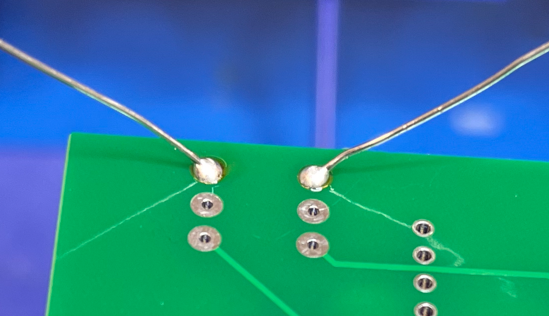
-
Feel free to trim the pins using wire snips. Cut right above the bead of solder left on the board.
-
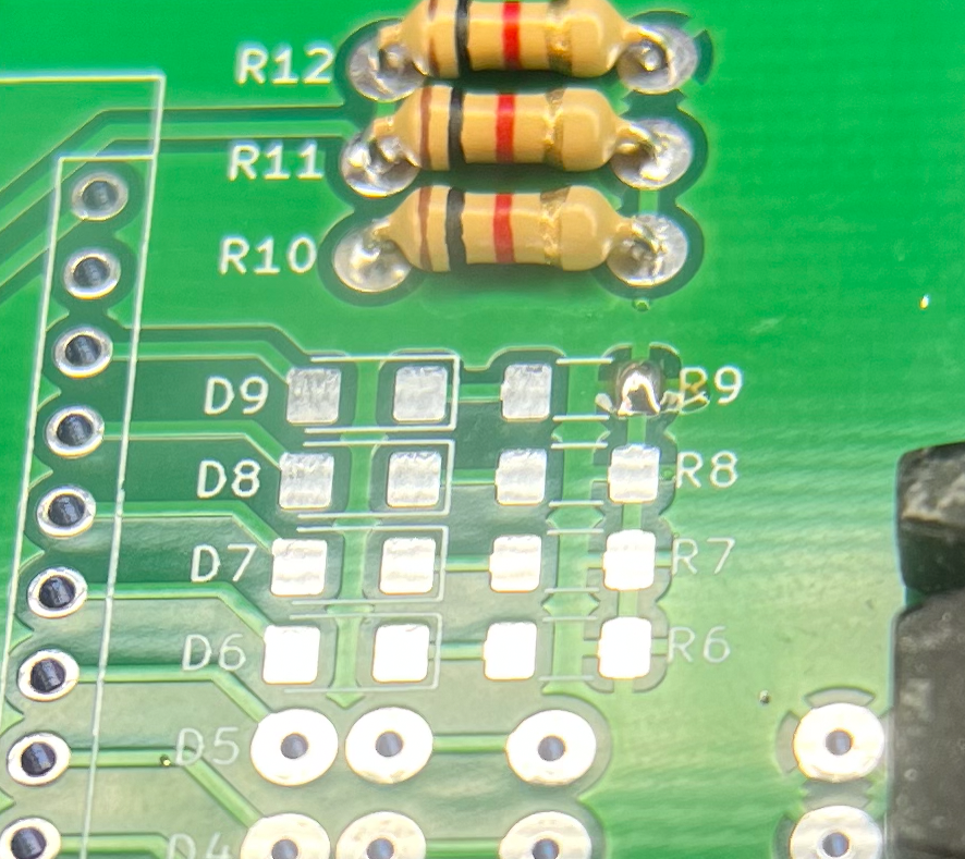
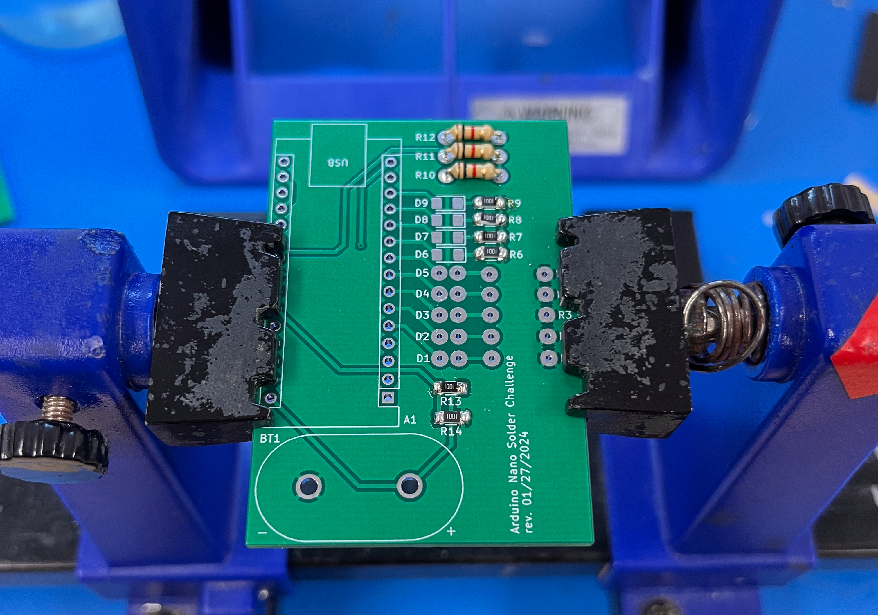
Repeat this step three times for resistors R10 and R11.
-
Now we are going to solder some surface mount components! These are a bit trickier than through hole components, so be careful! Start by heating one side of the surface mount pad for the resistor R9. It is probably easiest to add solder to the pad on the side you hold the soldering iron on.
- Using tweezers and a clean soldering iron tip, reheat the pad with solder on it, and then carefully slide the resistor into place while the solder is being heated. Remove the heat from the pad, so that your resistor is now held in place. Then carefully add solder to the other side.
- Repeat this process 5 more times for resistors R6-R8 and R13-R14.
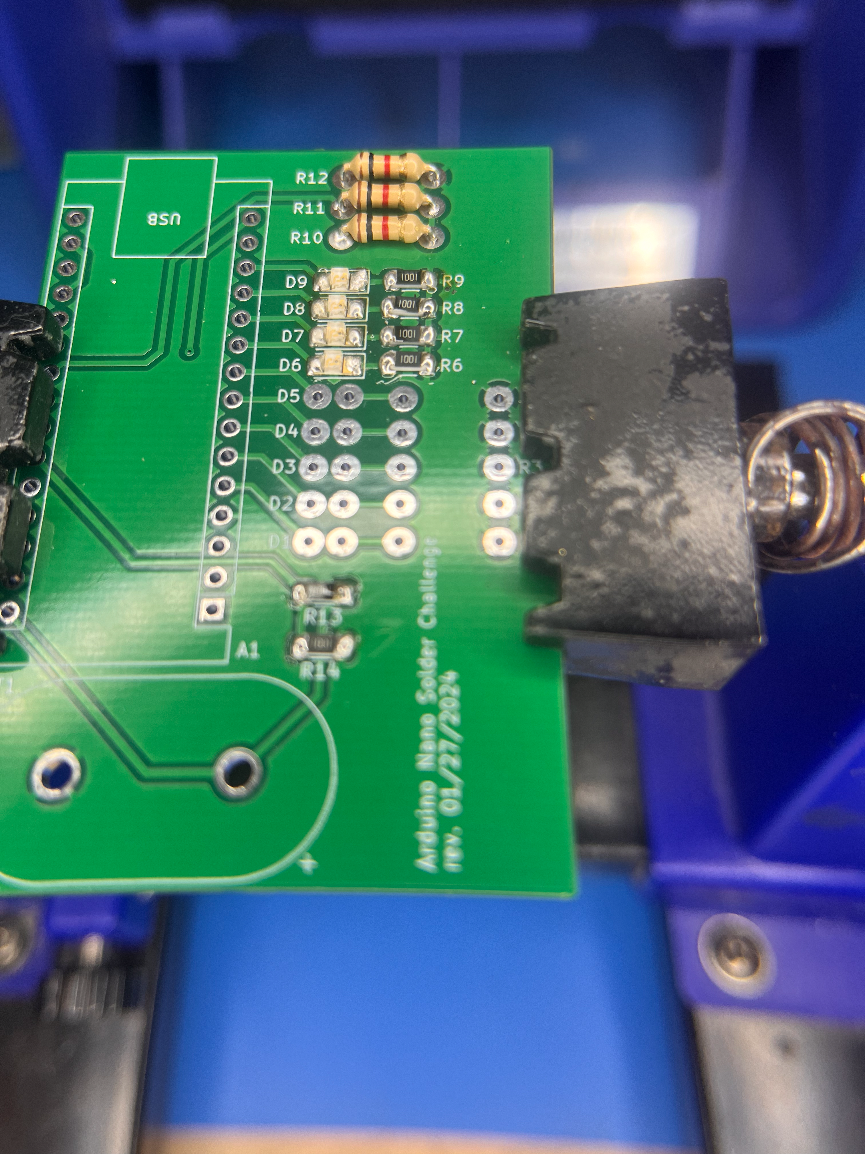
- Utilizing a similar procedure, you are going to solder four surface mount LEDs, D6-D9. Note that with LEDs polarity matters! There are green markings on the bottom of the surface mount LEDs. The side with a green box is the cathode (negative) side. And when looking at the top of the LED, there is a very small black dot, which is also the cathode side. This side should be oriented towards the resistors, or away from the Arduino.
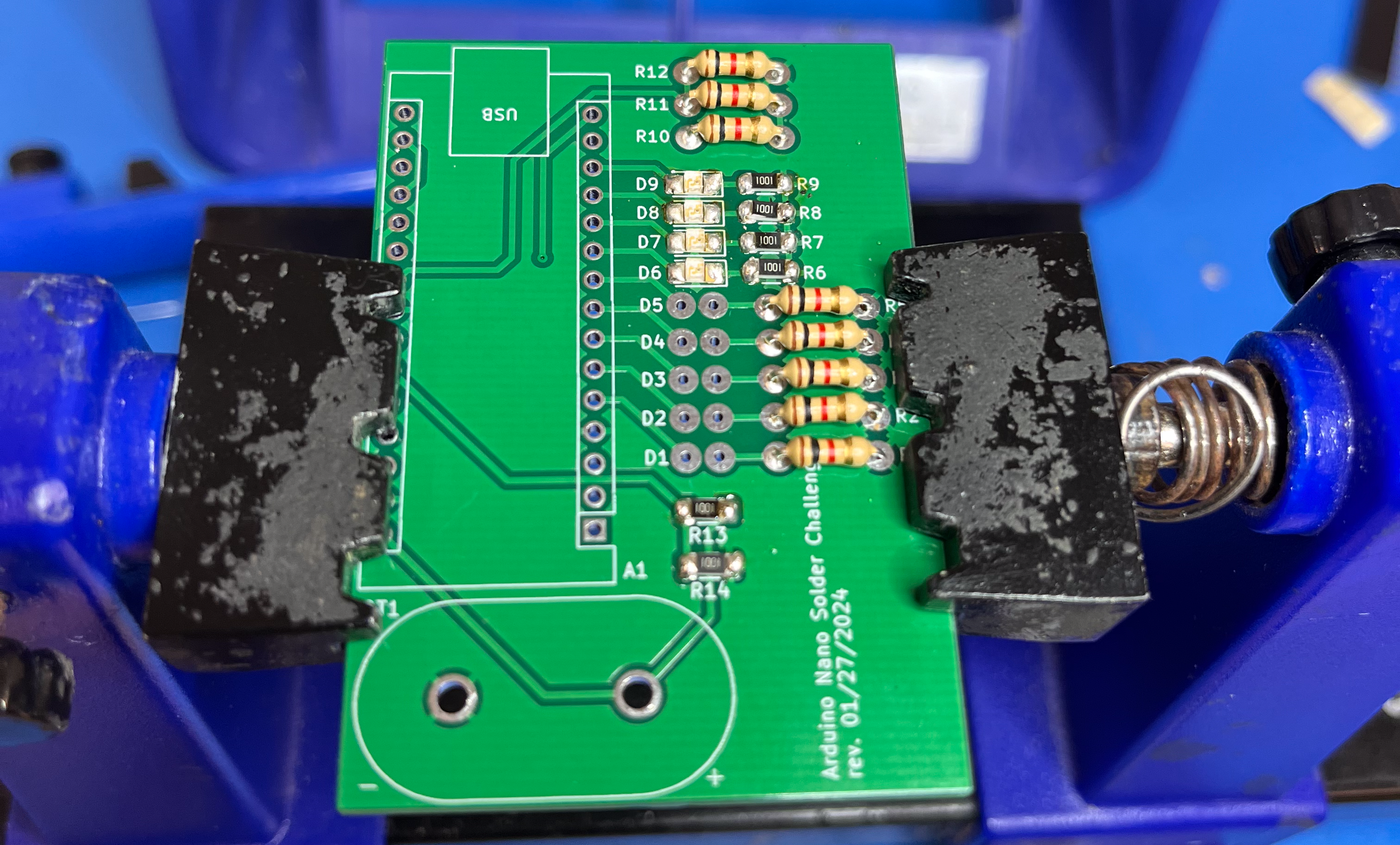
- Going back to through hole components now, add 5 more through-hole resistors to R1-R5 following the same procedure as before.
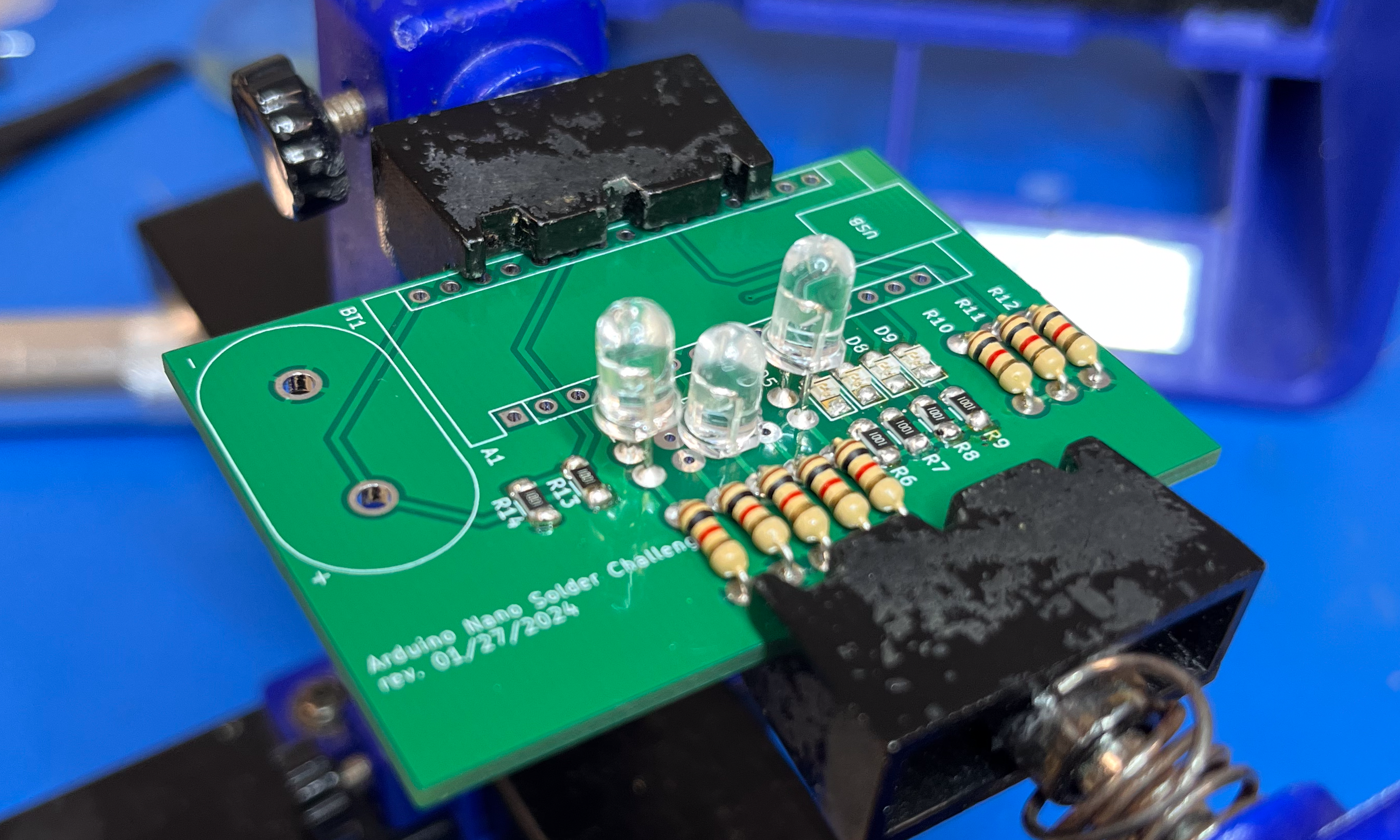
- Now we are going to add some through hole LEDs. In this case, the longer leg is the anode pin, which is the positive side. It should go into the hole closest to the Arduino, and the shorter leg should be in the hole closest to its paired resistor. Start by soldering in the middle LED, D3, and solder it so that it is flush to the board.
- Now we are going to solder D1 and D5. Repeat the same procedure as before, making note of polarity. These should stick out a little farther from the board to leave room for the last two LEDs.
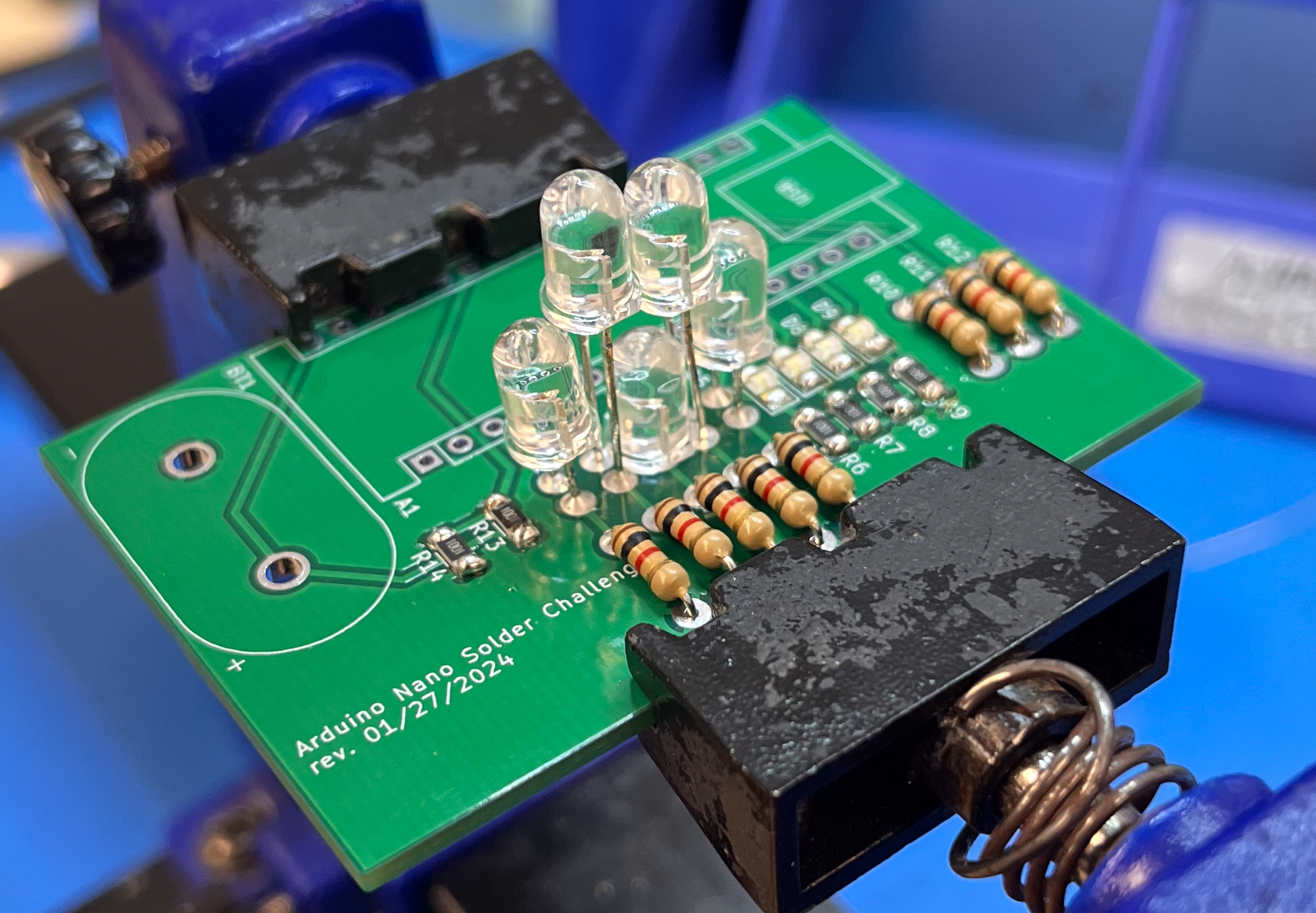
- Finally, we are going to solder D2 and D4. These LEDs will need to be positioned above the other three LEDs we have already soldered.
- Now we need to add some headers for the Arduino to fit into. You may need to get creative to hold the header in place and solder just one pin to secure it. Then solder the remaining pins of the header. Try to make this as straight as possible.
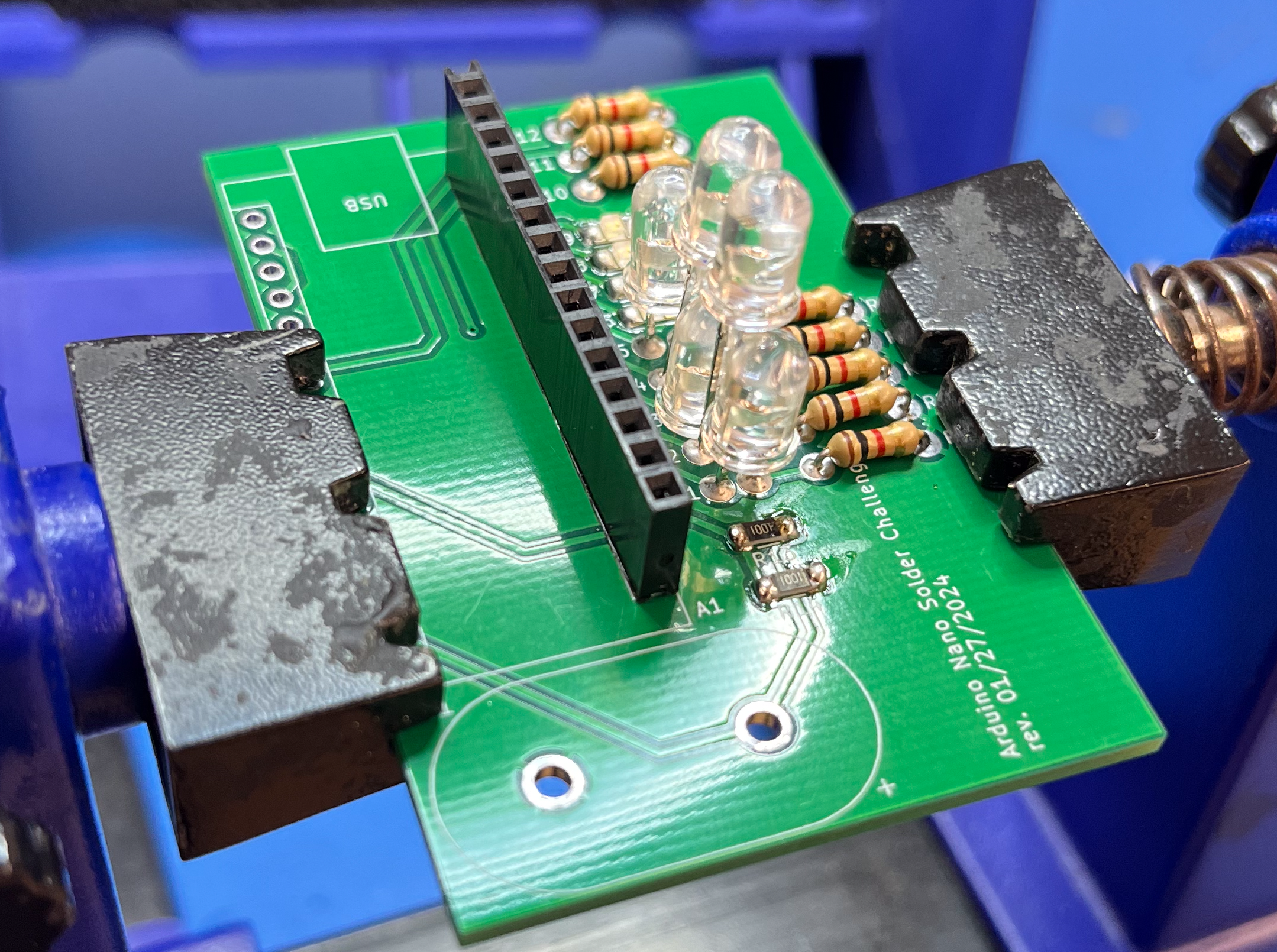
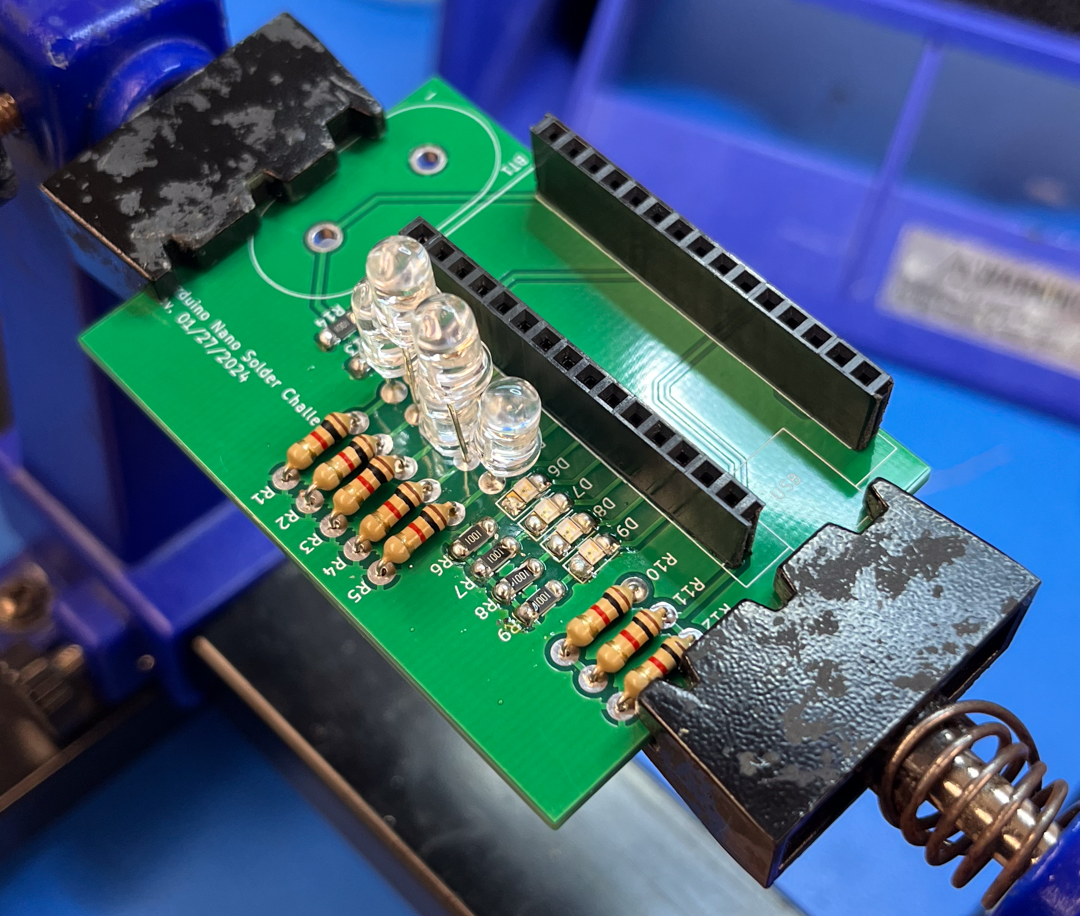
- Repeat this for the second header pin, and your board should look like this!
- Now we need to add the battery connector. The indicators on the PCB for polarity are referring to how the battery will sit in the connector, so you will need to flip the battery connector so this works properly. Insert it completely as shown below.
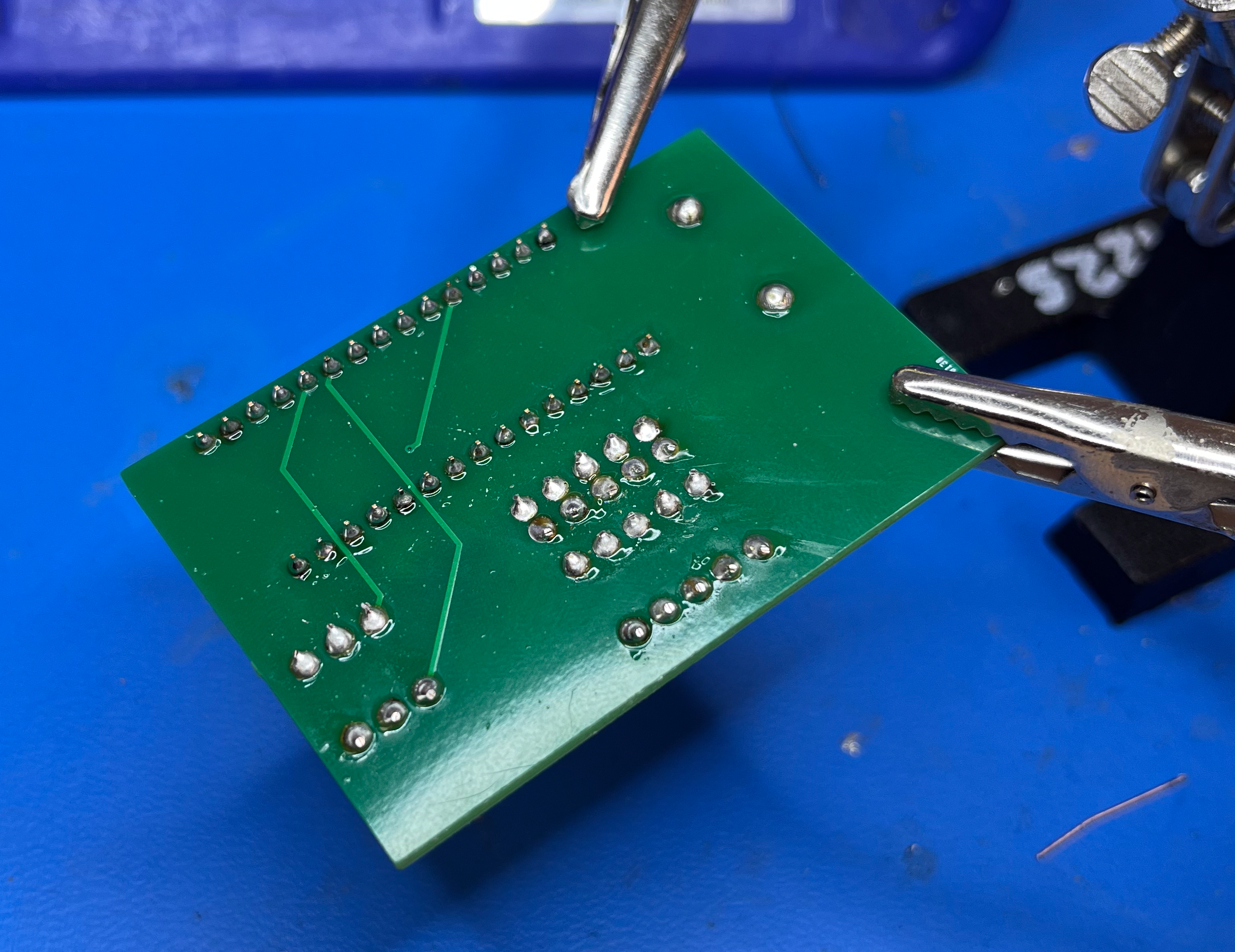
- Add solder to completely cover the back-side of the board’s battery connectors, as shown below.
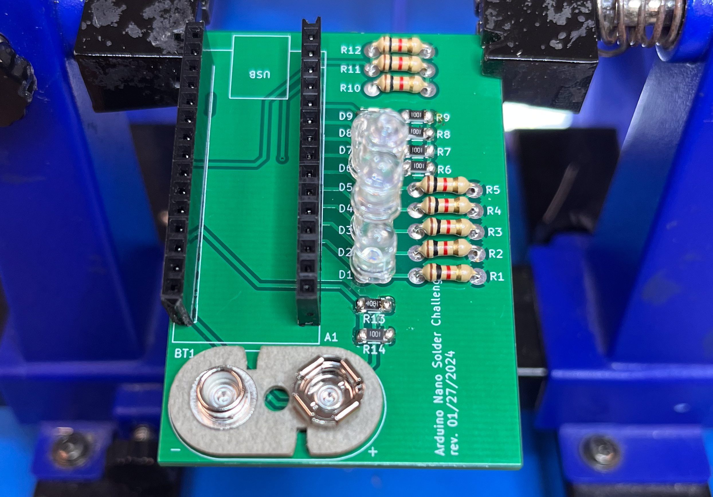
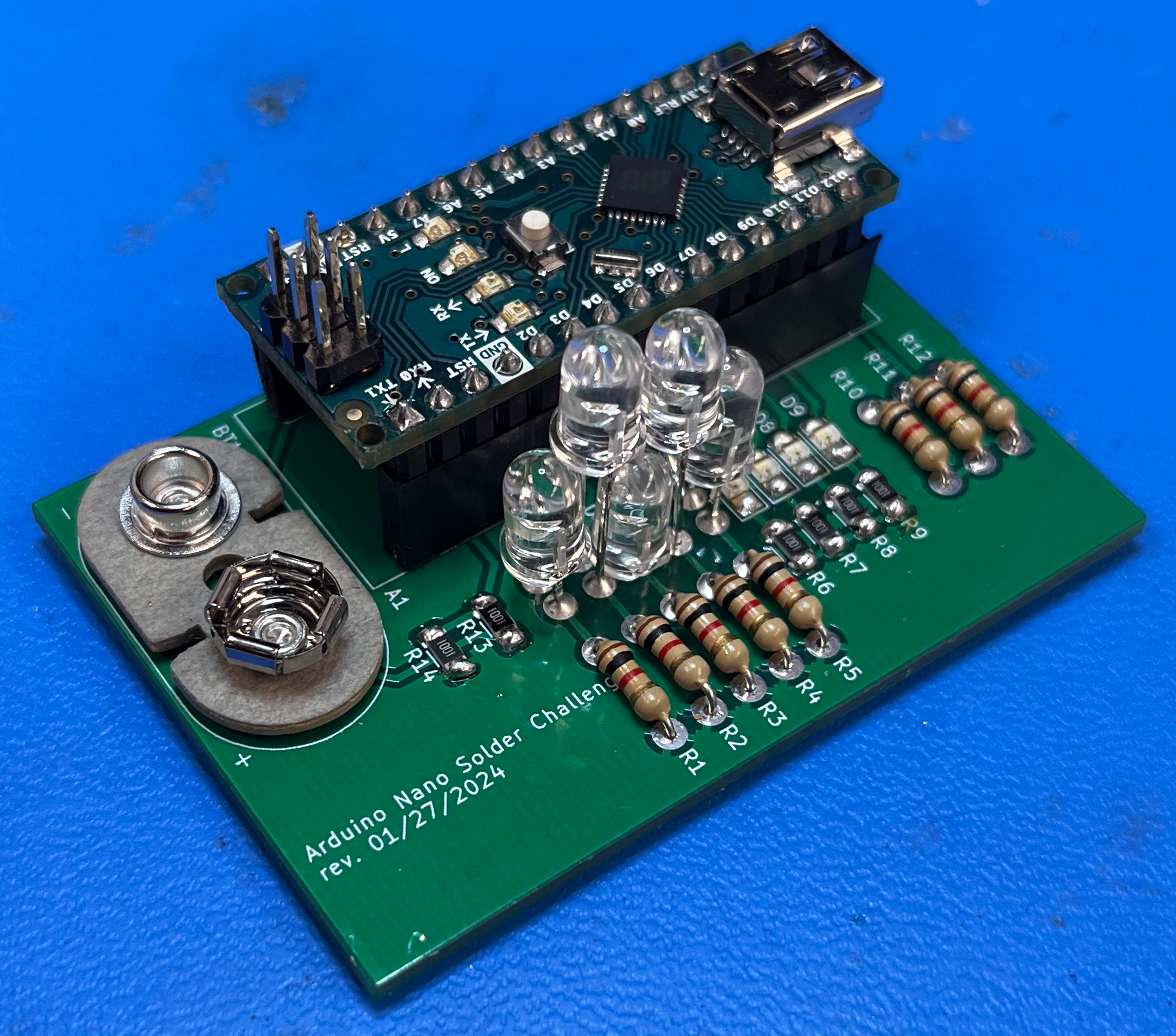
- You are now done with soldering! Your board should look like this:
- Upload the code Solder-Tester from the ENGR100-980 library to an Arduino, and then plug the Arduino, carefully, into the header pins on your completed board (USB should no longer be attached). When inserting a battery, you should see a pattern of lights flashing. Check with an instructor to see what these lights mean, or read the comments at the top of the code file!
Submission
-
You will receive points (out of 20) based on how the board functions and if the code runs correctly on your board.
-
Submit a picture of your board with all LEDs turned on in Canvas, a picture of the back of the board, and a picture of the front without the battery. Also leave a comment of the instructor’s name who checked your board!
Grading
- (10 points) 1pt for each operational LED (one freebie from onboard LED)
- (5 points) 1pt for each operational voltage divider
- 5pts for cleanliness of board
The following sequence should be observed:
-
Knight rider (9 LEDs turning off and on back and forth) twice - this tests LED connections (D1 - D9, R1 - R9) and digital pins on Arduino (D2 - D10)
-
The number of voltage divider circuits that are within tolerance (should be 5 lights and internal LED blinking 5 times) - this tests analog connections (A0 - A4) as well as some resistors.
-
0-9 LED scale indicating battery voltage (0-5v range, from 1/2 * Vbat voltage divider)
-
All 9 LEDs blink 5 times (indicating next reading is 5v)
-
0-9 LED scale indicating 5v pin voltage (0-5v range)
-
All 9 LEDs blink 2 times (indicating next reading is 5v * 2/3 voltage divider)
-
0-9 LED scale indicating 5v * 2/3 voltage divider reading (0-5v range)
-
All 9 LEDs blink 2 times (indicating next reading is 5v * 1/3 voltage divider)
-
0-9 LED scale indicating 5v * 1/3 voltage divider reading (0-5v range)
-
All 9 LEDs blink 3 times (indicating next reading is 3.3v)
-
0-9 LED scale indicating 3.3v pin voltage (0-5v range)
-
^^Repeats this loop^^