Engineering 100-980
Lab 5: Group B Portion
Building and testing the 5V and 3.3V LDO power board, and powering an Arduino from it.
Starting with this lab, we will no longer plug the 9V battery straight into the Arduino’s Vin pin. Instead, the battery will power the voltage regulator circuit you build below, and that circuit’s 5V output will power the Arduino through its 5V pin.
Contents
Materials
- 1 Arduino Nano
- 1 Breadboard
- 5.0V LDO
- 3.3V LDO
- 22 micro-Farad Capacitor
- Resistors for voltage divider circuit
- 9V Battery
- 1 Programming Cable (and adapters if necessary)
- A computer with the Arduino IDE installed and setup
- ENGR100-980 Arduino Library
- ENGR 100 980 KiCAD library
Safety
This lab involves working with a power supply which can provide higher voltages/currents than the Arduinos! Read the following sections carefully to maintain your safety and the safety of the components we are using.
It is very easy to accidentally short batteries when wires are connected to them. When not using the 9V battery, make sure that they have wire ends that are taped/secured, so the battery can not be shorted!
Procedure
1. Testing the LDOs
Make the circuit below on an (initially) empty breadboard. The power connection is coming from a 9V battery.
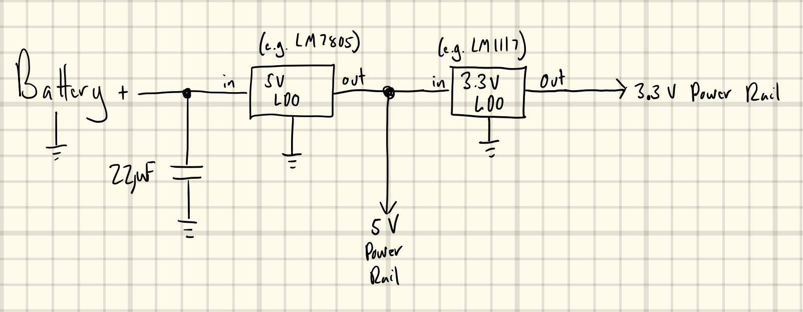
NOTE 1: We have a variety of through-hole LDOs. They may not match exactly what is specified in the diagram above. Google search for the LDOs that you have and verify their voltages and pin out configurations. It is up to you to get these right!
NOTE 2: The longer lead of the capacitor is the positive end. This means you should connect the longer lead to the side with a non-zero (non-ground) voltage, and the shorter lead to the ground line.
NOTE 3: Your system and your battery eventually need to share a common ground for you to get correct voltage measurements. Electrically connect all GND pins together to the battery’s negative terminal.
NOTE 4: We are now going to disconnect power whenever we rewire components on our breadboard!
Do NOT connect the battery to your circuit until an IA has checked it! Wiring an LDO or capacitor backwards can cause it to overheat, burst, or be destroyed. Build the circuit with the battery disconnected, then call an IA over to inspect it.
Once an IA has approved your circuit, connect the battery and use a multimeter to measure the actual outputs of the 5V and 3.3V LDO lines. If the 5V line is not exactly 5V, it can cause errors on the conversions of the sensor data from voltage into actual ”geophysical” units (C, %, g, etc.) You may want to use the reading from the 5V LDO in your calibration calculations.
A staff member will work with you on replacing the battery with a power supply.
2. Power Supply
The figure below shows a lab power supply. This is a device we frequently use in labs to power circuits: sometimes to avoid using the USB cable and a computer for power, and sometimes when we need a higher voltage than can be provided by the Arduino. There are multiple channels on the power supply, to allow for powering more than one device or produce more than one voltage at the same time.
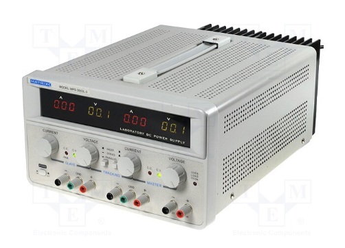
You will not be using a power supply at your workbench. Instead, bring your board to one of the IAs, who has a power supply set up for you. You will handle the power supply yourself, with the IA there to guide you. The power supply is current-limited at 500 mA and can cause serious damage if used improperly, so follow the steps below in order. Do not increase the power supply voltage above 10V.
Do not turn on the power supply until your connections have been verified by an IA!
- The IA will ask if you have read the outputs of your LDOs in the previous step. Have your readings ready; if you haven’t taken them yet, go back and do so before continuing.
- If so, disconnect the battery and wire the two terminals of the power supply to power your circuit in its place (Red = positive and Black = negative). Your two power rails are the 5V and 3.3V LDO outputs, so do not connect the power supply to a rail. Instead, plug the red wire into the same breadboard row where the battery’s positive lead was connected (the row feeding the LDO inputs), and the black wire into the row where the battery’s negative lead was connected. Do not connect them in holes adjacent to one another; we want to remove any possibility of the two wires accidentally coming in contact and shorting the circuit. Only adjust these wires while the power supply is off.
- Connect the multimeter to measure the output of the 5V LDO.
- BEFORE TURNING ON THE POWER SUPPLY, make sure all of its knobs are turned all the way to the left.
- Turn on the power supply and bring it up to 10V.
- Slowly drop the voltage of the power supply (rotate the knob slowly) until the output voltage of the 5V LDO reads more than 0.15V below its expected value (5V). Take note of this power supply voltage and label it as the 5V LDO’s value.
- Connect the multimeter to measure the output of the 3.3V LDO.
- Repeat what you did for the 5V LDO: start at the power supply voltage where you left off for the 5V LDO and keep decreasing it until the output of the 3.3V LDO reads more than 0.15V below its expected value (3.3V). Take note of this power supply voltage as well.
Turn the power supply off!
3. Battery Power
Disconnect the power supply, and add an Arduino to your power board. Make two voltage divider circuits, one hooked up to the Vin pin of the 5V LDO (i.e., this one will measure (half) the battery voltage) and one hooked up to the Vout pin of the 5V LDO (i.e., this should measure (half) 5V). Attach the output pin of the 3.3V LDO to an analog pin on the Arduino also. You should now be able to make a program that will measure the battery voltage, the 5V line voltage, and the 3.3V line voltage.
Remember to use color coding for your power lines and data lines. This will dramatically assist you in the debugging of your system if things don’t work.
Note that the output lines of the 5V and 3.3V lines are now your main power rails. The 5V LDO output line should be connected directly to the 5V line on the Arduino and there should be NO connections to the Vin pin on the Arduino. The 3.3V line does NOT get connected to the 3.3V line on the Arduino!
Once you have verified that everything is hooked up as it should be, add a 9V, battery to the top rail of your bread-board to power your LDO circuit and power on your Arduino. When you connect your battery, everything should turn on and start reporting data (although you can’t see it, since your computer is not hooked up yet). Hook up the USB to the Arduino and measure the battery voltage, 5V line voltage, and 3.3V line voltage using a program. Take a screenshot that shows that you are measuring the proper voltages on the different lines!
Take some pictures of this beautiful power board!
When Group A is ready to move on, disconnect all power from both boards. Then take both of your breadboards and move the analog jumpers running from your Arduino (battery, 5V line, and 3.3V line) into free analog pins on Group A’s Arduino, so that everything is wired into one microcontroller (you need not physically move the components, but rather just their jumpers, leaving two breadboards side by side. They can lock together!). Then connect a jumper from the 5V rail of Group A to the 5V rail of Group B (do this for the 3.3V rail and the GND rails as well). Note that the numbering of the analog pins does NOT matter. As one last final check, Group B’s original Arduino should have nothing plugged into it, so you can remove any jumpers remaining connecting it to power or GND, and nothing should be plugged into Group A’s Vin pin. The 9V battery now connects only to your power board. Once this is done, follow the link below to jump back into the normal lab manual together.